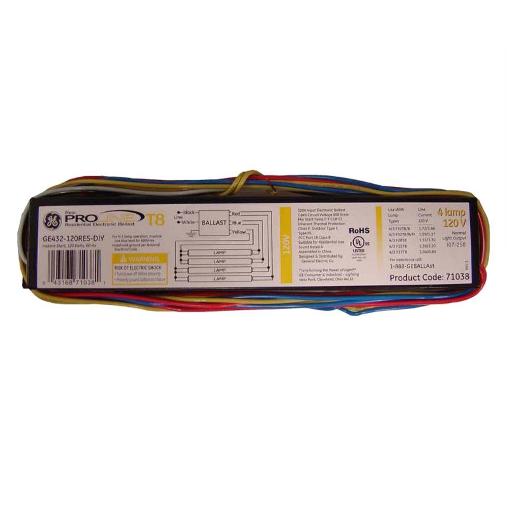
They are also one of the charter products of the nema premium ballast program. Optanium high efficiency instant start electronic fluorescent ballasts for t8 lamps engineered to optimize lighting performance and maximize energy savings optanium ballasts fully support the wide variety of t8 fluorescent lamps on the market.
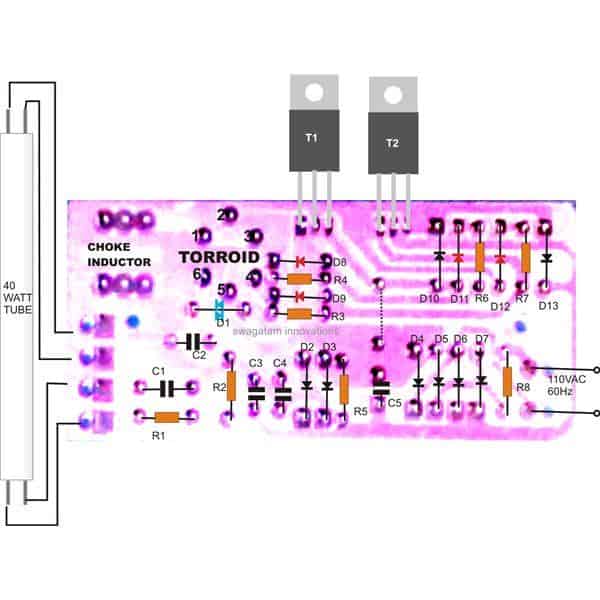
Cut the load and neutral wires from the ballast leaving a sucient amount of wire to connect back to the 110 vac power source.

You can find out more Diagram below
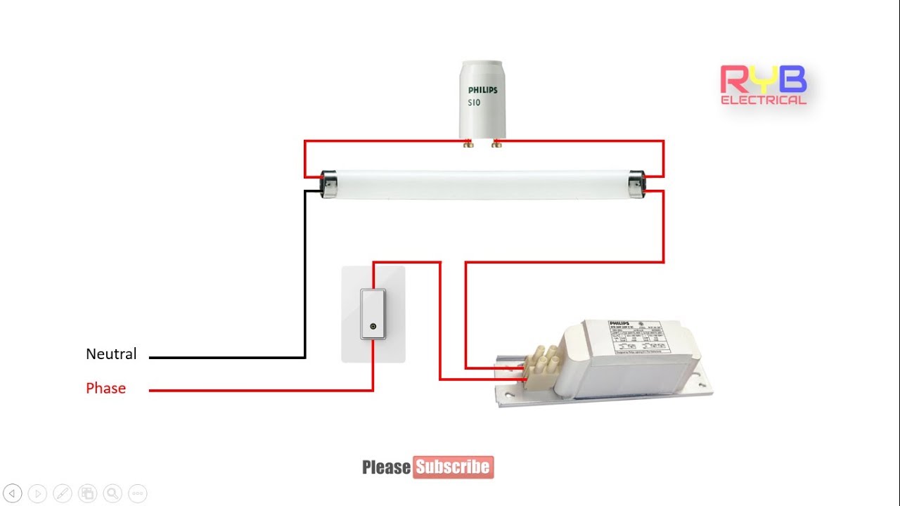
Pdf electronic ballast wiring diagram. 1 using the navigation window use the navigation window and select the emergency ballast for which the diagram is needed then scroll through the list of applications to find the. Diagrams for specific situations can be located within this pdf file by using the following methods. Wiring guidelines for em basic used with 50 hz magnetic ballasts and glow switch or electronic starters 1.
Cap all unused wires. Connection instructions led tube light installation ballast bypass. Electronic ballast magnetic ballast universal lighting technologies is a subsidiary of panasonic lighting americas a member of the panasonic corporation eco solutions company 2 lamp rapid start to 2 lamp electronic instant start retrofit wiring diagrams notes.
2 lamp t8 ballast wiring diagram ballast bypass wiring diagram inspirational t8 ballast wiring diagram l t8 ballast wiring. This means for example in a linear t8 or t5 luminaire the mains wiring. This is applicable for 2 lamp t12 rapid start to a 2 lamp electronic t8 system.
Facturer is listed for ac ballasts that have unique wiring arrangements. Diagrams for specific situations can be located within this pdf file by using the following methods. Connect black and blue wires as shown in the diagram.
Collection of 2 lamp t8 ballast wiring diagram. Ballast wiring diagram important this diagram is for reference purposes only. 1 using the navigation window use the navigation window and select the emergency ballast for which the diagram is needed then scroll through the list of applications to find the.
Mount the timer inside electrical box using 2 mounting screws provided. Depending upon line voltage connect the mounting strap green wire to either a the timer green wire for 120vac or b the timer greenyellow wire for 277vac and the ground. Ballast wiring should only be performed by a licensed electrician.
Jumper wires yellow yellow red blue blue 4 lamp programmed start t8 system red orange orange light blue light blue. Facturer is listed for ac ballasts that have unique wiring arrangements. Within the luminaire the switched and unswitched 50 hz supply wiring must be routed as short as possible and be kept as far away as possible from the lamp leads.
Click on the image to enlarge and then save it to your computer by right clicking on the image. F32t8 mark 5 programmed start electronic fluorescent ballasts designed for easy installation in new construction and retrofit settings our new and improved mark 5 ballasts for 1 2 and 3 32w 25w and 17w t8 lamps offer a wide range of features. Cap the red wire.
Cut back additional wiring on opposite side of ballast as the led tube lamp only requires power at one end.


0 comments:
Post a Comment