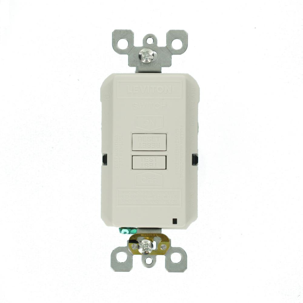
Trsgf15 line art with dimensions figure 4. Further they prevent resetting if once tripped the ground fault renders the device no longer functional.
Do not use it with aluminum wire.
You can find out more Diagram below
Cooper gfci schematic wiring diagram. Eatons ground fault circuit interrupter gfci receptacles are circuit interrupters designed to recognize a ground fault in your wiring and immediately break the flow of electricity thus protecting you from electrical shock. The gfcis features to prevent severe shock or electrocution always turn the power off at the service panel before working with wiring. Do not install this gfci receptacle on a yellow stickera circuit that powers life support.
If you are replacing an existing gfci outlet with a new one we suggest that you read our page about replacing a gfci outlet. Now available with self testing capability specification grade combination switchgfci receptacle is ul listed fully compliant with all latest ul 943 4th edition class a gfci ul 498 requirements and ul 508 for motor control switch horsepower rating. Wiring diagram gfci breaker new double pole mcb wiring diagram fresh.
You can also learn about wiring gfci outlets in the following 7 steps. Description amps volts color suffix trsgf15 nema 5 15r duplex self test gfci back side wire 15 125 a b bk gy la rb sg v w trsgf20 nema 5 20r duplex self test gfci back side wire. D2pb series wiring diagram for model m2 circuit breaker panelboard 12 circuit single phase 3 wire if 428 revision 1.
Two pole gfci breaker wiring diagram collections of wiring diagram gfci outlet valid 2 pole gfci breaker wiring diagram. Tamper resistant self test gfci receptacles back side wire catalog no. Use this gfci receptacle with copper or copper clad wire.
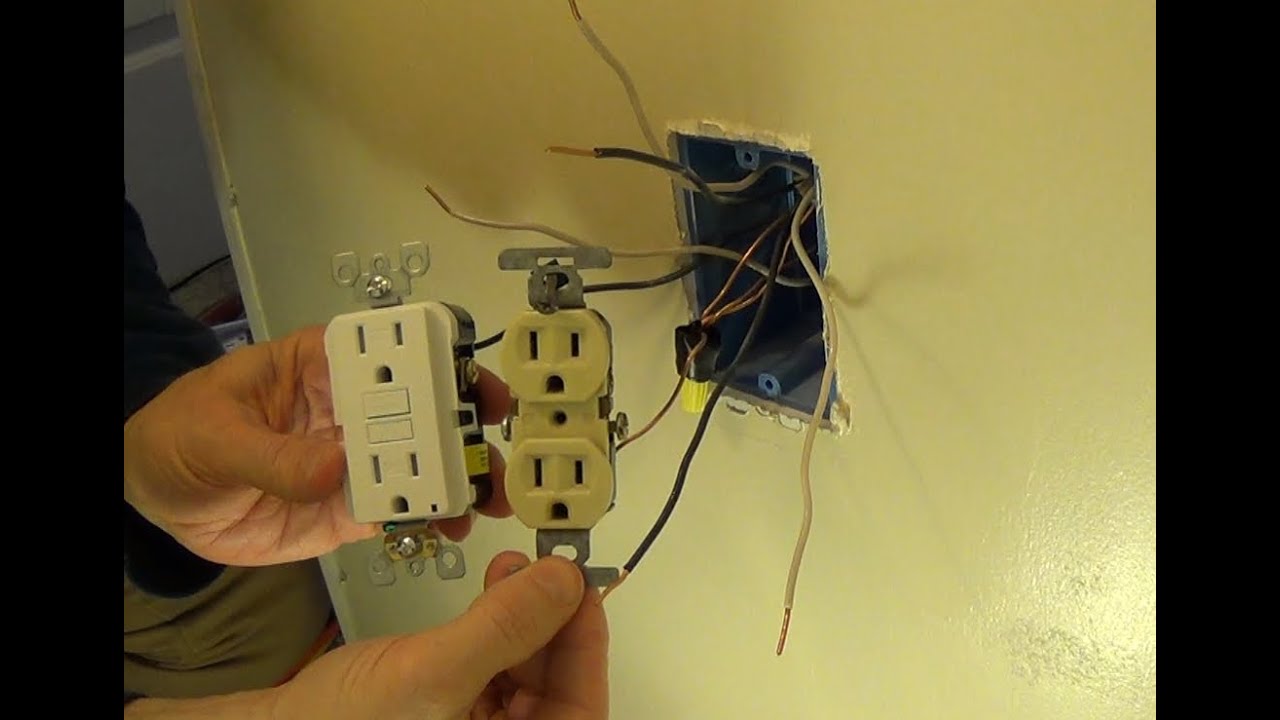
If a load plugged into the outlet or the disposal causes a short the whole device will trip and neither will work until the danger is removed. Wiring a gfci receptacle is a little more complicated than hooking up a regular outlet but easily learned once explained. Gfci wiring diagram best leviton wiring diagrams download with.
D2pb series wiring diagram for model m2 circuit breaker panelboard 24 circuit single phase 3 wire. Wet location gfci. 2 pole mcb wiring diagram refrence gfci breaker wiring diagram best.
This diagram illustrates the wiring for a cooper gfci combo switch device to control a garbage disposal. Gfs1 m4 ground fault circuit interrupter if 1511 revision 2. Installation maintenance sheets.
Eaton gfcis are tested to the highest standards and provide. Wiring diagrams figure 3. Wiring for a switch and gfci receptacle in the same box is also shown.
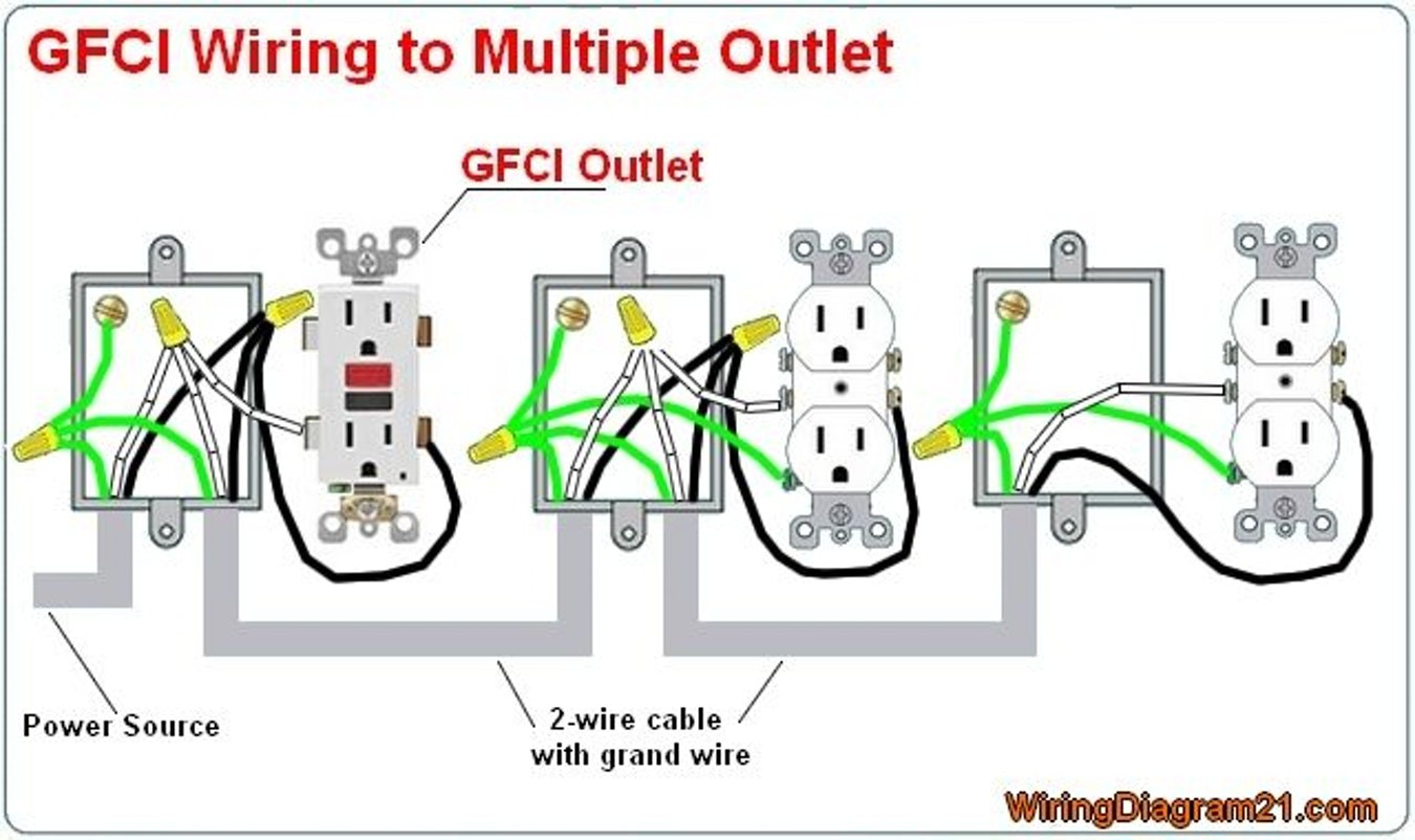
How to wire gfci outlets. This page contains wiring diagrams for ground fault circuit interrupter gfci receptacles. Included are diagrams for multiple gfcis a protected standard duplex receptacle and a protected light fixture.
Here the gfci outlet the switch and disposal are all protected from ground faults.


0 comments:
Post a Comment