This is required because there is no internal crystal present in pic 16f873a. V guard stabilizers are unmatched in every sense.
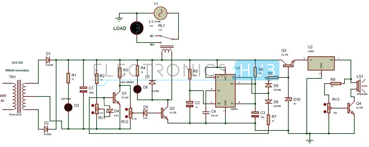
For the microcontroller circuit we use an external crystal of 4 mhz.

You can find out more Diagram below
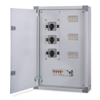
V guard voltage stabilizer circuit diagram. But of course it can be very amusing to build one at home all by you and see it actually working. With features like automatic restart turn on delay time delay system and high low voltage cut off that provide efficient and reliable protection for electronic appliances against voltage problems. Halo friends in todays video you are told about the v guard companys stabilizer repairing.
The heart of the stabiliser is ic1 lm3914 bar display driver. The circuit diagram of a solid state voltage stabiliser is shown in fig2. It is a power appliance used to feed constant voltage current to electrical appliances.
Bridge rectifier is employed to convert ac to dc and 1000uf capacitor is used to filter ac ripples. You can repair any companys stabilizer through this video as this video shows how any company you. It is used as led type bar graph voltmeter with lower voltage and upper voltage settings through presets vr1 and vr2.
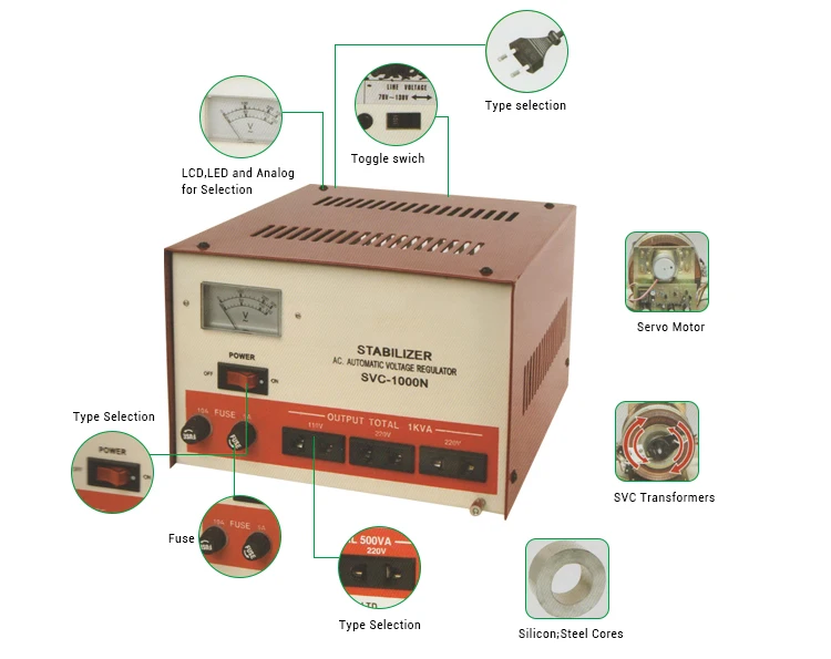
What is a voltage stabilizer. The largest selling and trusted stabilizer brand of india v guard offers the best technology. R1 limits the surge current while r2 decides the triggering voltage to t1 if the current consumption crosses the 15 amp mark t1 conducts and.
Power supply is erratic at most places in india with volt. The circuit of an automatic voltage stabilizer avs described in this article is in fact very simple in design reasonably precise and will give a good. Construction of voltage stabilizer with circuit diagram complete guide.
There are huge varieties of voltage stabilizers available in the market and surely its not a big deal to procure one according to the needs. Protecting them from damage because of voltage fluctuations. The circuit diagram shows a rather simple configuration where the ic 317 has been wired in its standard voltage regulator mode.
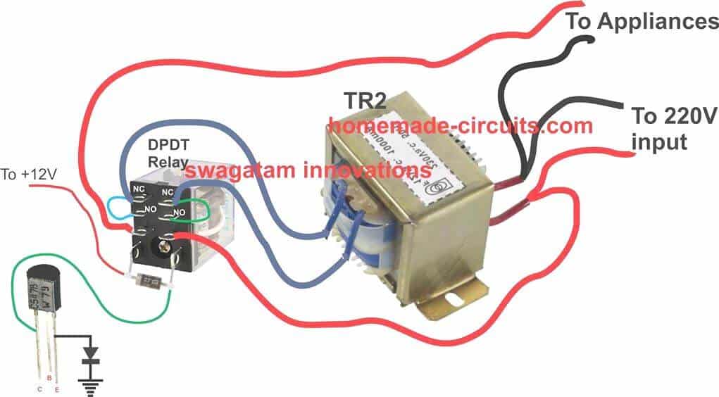
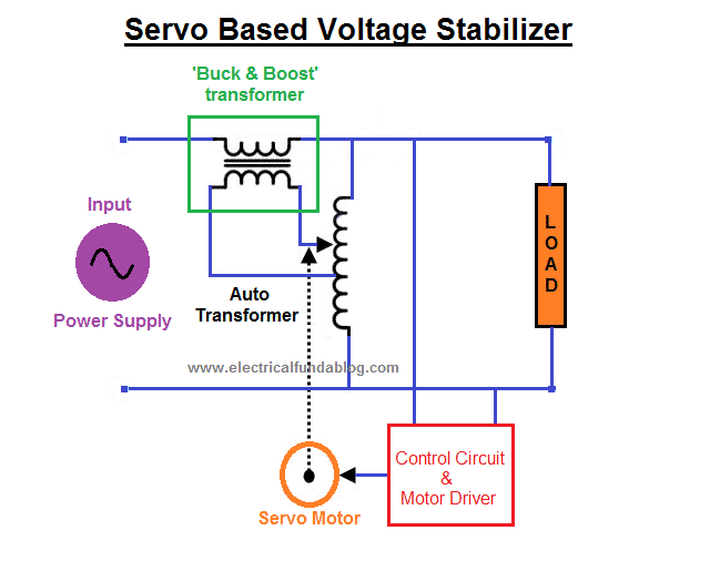
Make this voltage stabilizer circuit for your car. A 12v step down transformer is used to drive the stabilizer circuit and the same transformer is used to analyze the input line voltage. The embedding of microprocessor chip technology and power electronic devices in the design of intelligent ac voltage stabilizers or automatic voltage regulators avr led to produce high quality stable electric power supply in the event of significant and continuous deviation of mains voltage.
This is a relay type voltage stabilizer circuit diagram. Automatic voltage stabilizer circuit diagram voltage stabilizer circuit operation.


0 comments:
Post a Comment